Specifications. Levels with micrometric supply of ampoule
GOST 11196-74
Group P54
INTERSTATE STANDARD
LEVELS WITH MICROMETRIC AMPOULE FEEDING
Specifications
Levels with micrometrical feed of ampule.
Specifications
OKP 39 4424
Introduction date 1976-01-01
INFORMATION DATA
1. DEVELOPED AND INTRODUCED by the Ministry of Machine Tool and Tool Industry
2. APPROVED AND INTRODUCED BY Decree of the State Committee for Standards of the Council of Ministers of the USSR dated June 13, 1974 N 1459
Change No. 4 was adopted by the Interstate Council for Standardization, Metrology and Certification (minutes No. 3 dated February 18, 1993)
Voted to accept:
State name | Name of national authority |
The Republic of Azerbaijan | Azgosstandart |
Republic of Armenia | Armstate standard |
Republic of Belarus | State Standard of Belarus |
Gruzstandard |
|
The Republic of Kazakhstan | State Standard of the Republic of Kazakhstan |
The Republic of Moldova | Moldovastandard |
Russian Federation | Gosstandart of Russia |
Turkmenistan | Main State Inspectorate of Turkmenistan |
The Republic of Uzbekistan | Uzgosstandart |
State Standard of Ukraine |
3. INSTEAD OF GOST 11196-65 and GOST 5.878-71
4. REFERENCE REGULATIONS AND TECHNICAL DOCUMENTS
Item number |
|||
working surfaces of bases | non-working surfaces adjacent to work surfaces |
||
2.18. The outer raw surfaces of the base of the levels must have an anti-corrosion coating. On the surfaces of the parts of the levels there should be no defects that worsen the appearance or performance.
2.19. The body of levels must undergo a stabilization operation in order to relieve internal stresses.
2.18, 2.19.
2.20. 2.20a, 2.21, 2.22, 2.22a, 2.22b. (Excluded, Rev. N 4).
2.23. (Deleted, Rev. N 2).
2.24. Operating conditions of the levels corresponding to the requirements of Table 2: ambient temperature - (20±3) °С; relative air humidity - no more than 80% at a temperature of 25 °C.
(Changed edition, Rev. N 2, 3).
2.25. Completeness
2.25.1. Each level must be accompanied by a passport in accordance with GOST 2.601
2.26. Marking
2.26.1. At each level must be applied:
serial number according to the numbering system of the manufacturer;
year of issue or its designation;
value of division.
2.26.2. The case must bear:
trademark of the manufacturer;
level division price;
designation of this standard.
2.27. Package
2.27.1. Packing levels - according to GOST 13762.
2.27.2. Levels must be packed in cases.
2.25, 2.25.1, 2.26-2.26.2, 2.27-2.27.2. (Introduced additionally, Izm, N 4).
2a. COMPLETENESS
2a.1. Each level must be accompanied by a passport in accordance with GOST 2.601, including instructions for use.
Section 2a. (Introduced additionally, Rev. N 1).
2b. ACCEPTANCE
2b.1. To verify compliance with the requirements of this standard, the levels should be subjected to state tests, acceptance control and periodic tests.
(Changed edition, Rev. N 2).
2b.1a. State tests - according to GOST 8.383 and GOST 8.001.
(Introduced additionally, Rev. N 2).
2b.2. During acceptance control, each level should be checked for compliance with the requirements of clauses 2.2-2.5, 2.9; 2.12; 2.13; 2.15; 2.17 (in terms of surface roughness); 2.18; 2.25.1.
(Changed edition, Rev. N 4).
2b.3. Periodic tests are carried out at least at three levels of each type from among those that have passed the acceptance control at least once every three years for compliance with all the requirements of this standard.
The tests are considered satisfactory if all levels tested meet these requirements.
(Changed edition, Rev. N 2, 3, 4).
2c. CONTROL AND TEST METHODS
2 in 1. Verification of levels should be carried out according to the methods specified in GOST 15982.
2v.2. When checking the influence of transport shaking, a shock stand is used that creates shaking with an acceleration of 30 m/s at a frequency of 80-120 beats per minute.
The levels in the package are attached to the stand and tested with a total number of impacts of 15000. After the test, the error of the levels should not exceed the values \u200b\u200bspecified in Table 2.
(Changed edition, Rev. N 2).
2v.3. The impact of environmental climatic factors during transportation is checked in climatic chambers.
Level tests are carried out in a transport container in the following mode: at a temperature of minus (50 ± 3) °С, plus (50 ± 3) °С and at a humidity of (95 ± 3)% and a temperature of 35 °С. Exposure in the climatic chamber for each type of test - at least 2 hours. After the test, the level errors should not exceed the values \u200b\u200bspecified in Table 2.
(Changed edition, Rev. N 3, 4).
2.6.4. (Deleted, Rev. N 3).
3. TRANSPORT AND STORAGE
3.1. Transportation and storage of levels - according to GOST 13762.
Section 3. (Changed edition, Rev. N 4).
4. MANUFACTURER WARRANTY
4.1. The manufacturer must ensure that the levels comply with the requirements of this standard, subject to the rules for their storage, transportation and operation established by the standard.
(Changed edition, Rev. N 2).
4.2. Warranty period of operation - 18 months from the date of putting the levels into operation.
(Changed edition, Rev. N 1, 2, 3).
The text of the document is verified by:
official publication
M.: IPK Standards Publishing House, 1999
Levels with micrometric ampoule supply, GOST 11196-74
Metrology. GOST 11196-74: Levels with micrometric ampoule feed. Specifications. OKS: Metrology and measurements. Physical phenomena, Linear and angular measurements. GOSTs. Levels with micrometric supply of the ampoule. Technical.... class=text>
GOST 11196-74
Levels with micrometric supply of the ampoule. Specifications
GOST 11196-74
Group P54
INTERSTATE STANDARD
LEVELS WITH MICROMETRIC AMPOULE FEEDING
Specifications
Levels with micrometrical feed of ampule.
Specifications
OKP 39 4424
Introduction date 1976-01-01
INFORMATION DATA
1. DEVELOPED AND INTRODUCED by the Ministry of Machine Tool and Tool Industry
2. APPROVED AND INTRODUCED BY Decree of the State Committee for Standards of the Council of Ministers of the USSR dated June 13, 1974 N 1459
Change No. 4 was adopted by the Interstate Council for Standardization, Metrology and Certification (minutes No. 3 dated February 18, 1993)
Voted to accept:
State name | Name of national authority |
The Republic of Azerbaijan | Azgosstandart |
Republic of Armenia | Armstate standard |
Republic of Belarus | State Standard of Belarus |
Gruzstandard |
|
The Republic of Kazakhstan | State Standard of the Republic of Kazakhstan |
The Republic of Moldova | Moldovastandard |
Russian Federation | Gosstandart of Russia |
Turkmenistan | Main State Inspectorate of Turkmenistan |
The Republic of Uzbekistan | Uzgosstandart |
State Standard of Ukraine |
3. INSTEAD OF GOST 11196-65 and GOST 5.878-71
4. REFERENCE REGULATIONS AND TECHNICAL DOCUMENTS
Item number |
|
GOST 2.601-95 | |
GOST 8.001-80* | |
GOST 8.383-80* | |
GOST 2386-73 | 2.6, 2.7; 2.8; 2.17 |
GOST 13762-86 | |
GOST 15982-70 |
_______________
* On the territory of the Russian Federation, PR 50.2.009-94 is in force, hereinafter in the text. - Note.
5. The limitation of the validity period was removed according to protocol N 5-94 of the Interstate Council for Standardization, Metrology and Certification (IUS 11-12-94)
6. REPUBLICATION (January 1999) with Amendments No. 1; 2, 3, 4, approved in May 1981, December 1984, August 1989, December 1995 (IUS 8-81, 4-85, 12-89, 2-96)
This standard applies to levels with micrometric ampoule feed (hereinafter referred to as levels) designed to measure the inclinations of flat and cylindrical surfaces relative to a horizontal position.
The requirements of this standard, except for paragraphs 2.10, 2.11, 2.16, are mandatory, the requirements of paragraphs 2.10, 2.11, 2.16 of this standard are recommended.
1. TYPES, MAIN PARAMETERS AND DIMENSIONS
1.1. Levels must be made of two types with the dimensions indicated in Table 1a:
1 - with a division value of 0.01 mm / m (Fig. 1);
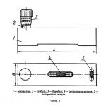
2 - with a division value of 0.10 mm / m (Fig. 2).
Table 1a
Level type | Cylindrical surface diameter |
||
20 to 110 |
|||
Damn.1. Level with division value 0.01 mm/m
1 - limb; 2 - base; 3 - dial revolution counter scale; 4 - longitudinal ampoule;
5 - transverse ampoule; 6 - optical device
Damn.1
Damn.2. Level with division value 0.10 mm/m
1 - base; 2 - stem; 3 - drum; 4 - longitudinal ampoule;
5 - transverse ampoule
Damn.2
Note. Drawings 1 and 2 do not define the design of the levels.
1.2. The main parameters of the levels must correspond to those indicated in Table 1.
Table 1
mm/m (deg)
Note. Approximate values are given in parentheses.
Type 1 level symbol example
Level 1 GOST 11196-74
1.3. On the working surfaces of the bases of the levels there must be prismatic grooves for installation on cylindrical surfaces with a diameter according to Table 1a.
1-1-1.3.
2. TECHNICAL REQUIREMENTS
2.1. The length of the bubble must remain within the field of view for levels of type 1 and within the graduated part of the ampoule for levels of type 2 in the temperature range from plus 35 to minus 5 °C.
2.1a. Levels should be manufactured in accordance with the requirements of this standard according to working drawings approved in the prescribed manner.
2.2. The level error in the forward or reverse stroke of the micrometer screw, at ambient temperature (20 ± 2) ° C and relative humidity up to 80%, should not exceed the values \u200b\u200bspecified in Table 2.
table 2
2.3. The design of the levels should provide the ability to set the scale to the zero position when the level is horizontal with a deviation of no more than 2/5 of a division for type 1 and no more than 1/5 of a division for type 2.
2.4. At the zero position of the levels of type 2, the zero stroke of the drum must coincide with the longitudinal stroke of the stem, and the zero stroke of the stem must be visible in its entirety, and the distance from the end of the conical part of the drum to the edge of the stroke closest to the end should not exceed 0.15 mm.
2.5. When the level is rotated relative to a horizontally located cylinder by ±5 °С (in the presence of a transverse ampoule, by an angle within the scale of the transverse ampoule), the change in type 1 level readings should not exceed 1/2 division and type 2 - 1/4 division.
2.6. Cylindrical simple ampoules (ACP) that meet the technical requirements of GOST 2386 should be used as a longitudinal ampoule in type 1 levels.
2.7. As a longitudinal ampoule in type 2 levels, cylindrical chamber ampoules (ACC) or cylindrical compensated ampoules (ACC) that meet the technical requirements of GOST 2386 should be used.
2.8. As a transverse ampoule of levels, cylindrical simple ampoules (ADC) with a division value from 3 "to 6" should be used, corresponding to the technical requirements of GOST 2386.
2.9. The installation error of the transverse ampoule relative to the working surface of the base of the levels should not exceed 1/2 division of the ampoule scale.
2.2-2.9. (Changed edition, Rev. N 2).
2.10. The type 1 level dial must have 100 divisions. Every fifth division should be marked with an extended stroke, and every tenth with an extended stroke and the corresponding number.
The speed scale must have at least 20 divisions. Every fifth division of the revolution scale must be marked with an elongated stroke and the corresponding number.
2.11. The type 2 level drum scale should have 50 divisions. The scale marks should reach the edge of the bevel of the drum. Every fifth division should be marked with an elongated stroke and the corresponding number.
Digitization of the scale should be double and different in color.
The stem must be marked with a longitudinal stroke and at least 6 divisions on either side of zero, each of which must correspond to a level slope of 5 mm/m.
(Changed edition, Rev. N 2).
2.12. The width of the strokes of the limb scale and the strokes of type 1 level scale indicators, as well as the longitudinal stroke on the stem and the strokes of the scales on the type 2 level drum must be equal to (0.2 ± 0.05) mm.
The difference in the width of individual strokes within the same scale, as well as in the width of the stroke of the dial indicator scale and strokes of the type 1 level dial and in the width of the longitudinal stroke and strokes on the type 2 level drum should not exceed 0.05 mm.
(Changed edition, Rev. N 3).
2.13. The distance from the upper edge of the edge of the scale of the dial to the surface of its indicator for levels of type 1 and from the top edge of the edge of the drum to the stem at the longitudinal stroke for levels of type 2 should not exceed 0.45 mm.
2.14. Surfaces on which strokes and numbers are applied should not be shiny.
2.15. The flatness tolerance of the working surfaces of the base of the levels should not exceed 0.002 mm for levels of type 1 and 0.006 mm for levels of type 2.
Convexity of working surfaces is not allowed.
2.16. A notch with a length of no more than /2 is allowed in the middle part of the working surfaces.
2.14-2.16. (Changed edition, Rev. N 2).
2.17. The hardness and roughness of the surfaces of the base of the levels must correspond to those indicated in Table 3.
Table 3
Level type | Working hardness | Roughness according to GOST 2789, microns |
|
working surfaces of bases | non-working surfaces adjacent to work surfaces |
||
2.18. The outer raw surfaces of the base of the levels must have an anti-corrosion coating. On the surfaces of the parts of the levels there should be no defects that worsen the appearance or performance.
2.19. The body of levels must undergo a stabilization operation in order to relieve internal stresses.
2.18, 2.19. (Changed edition, Rev. N 2).
2.20. 2.20a, 2.21, 2.22, 2.22a, 2.22b. (Excluded, Rev. N 4).
2.23. (Deleted, Rev. N 2).
2.24. Operating conditions of the levels corresponding to the requirements of Table 2: ambient temperature - (20±3) °С; relative air humidity - no more than 80% at a temperature of 25 °C.
(Changed edition, Rev. N 2, 3).
2.25. Completeness
2.25.1. Each level must be accompanied by a passport in accordance with GOST 2.601, including instructions for use.
2.26. Marking
2.26.1. At each level must be applied:
serial number according to the numbering system of the manufacturer;
year of issue or its designation;
value of division.
2.26.2. The case must bear:
trademark of the manufacturer;
level division price;
designation of this standard.
2.27. Package
2.27.1. Packing levels - according to GOST 13762.
2.27.2. Levels must be packed in cases.
2.25, 2.25.1, 2.26-2.26.2, 2.27-2.27.2. (Introduced additionally, Izm, N 4).
2a. COMPLETENESS
2a.1. Each level must be accompanied by a passport in accordance with GOST 2.601, including instructions for use.
Section 2a. (Introduced additionally, Rev. N 1).
2b. ACCEPTANCE
2b.1. To verify compliance with the requirements of this standard, the levels should be subjected to state tests, acceptance control and periodic tests.
(Changed edition, Rev. N 2).
2b.1a. State tests - according to GOST 8.383 and GOST 8.001.
(Introduced additionally, Rev. N 2).
2b.2. During acceptance control, each level should be checked for compliance with the requirements of clauses 2.2-2.5, 2.9; 2.12; 2.13; 2.15; 2.17 (in terms of surface roughness); 2.18; 2.25.1.
(Changed edition, Rev. N 4).
2b.3. Periodic tests are carried out at least at three levels of each type from among those that have passed the acceptance control at least once every three years for compliance with all the requirements of this standard.
The tests are considered satisfactory if all levels tested meet these requirements.
(Changed edition, Rev. N 2, 3, 4).
2c. CONTROL AND TEST METHODS
2 in 1. Verification of levels should be carried out according to the methods specified in GOST 15982.
2v.2. When checking the influence of transport shaking, a shock stand is used that creates shaking with an acceleration of 30 m/s at a frequency of 80-120 beats per minute.
The levels in the package are attached to the stand and tested with a total number of impacts of 15000. After the test, the error of the levels should not exceed the values \u200b\u200bspecified in Table 2.
(Changed edition, Rev. N 2).
2v.3. The impact of environmental climatic factors during transportation is checked in climatic chambers.
Level tests are carried out in a transport container in the following mode: at a temperature of minus (50 ± 3) °С, plus (50 ± 3) °С and at a humidity of (95 ± 3)% and a temperature of 35 °С. Exposure in the climatic chamber for each type of test - at least 2 hours. After the test, the level errors should not exceed the values \u200b\u200bspecified in Table 2.
(Changed edition, Rev. N 3, 4).
2.6.4. (Deleted, Rev. N 3).
3. TRANSPORT AND STORAGE
3.1. Transportation and storage of levels - according to GOST 13762.
Section 3. (Changed edition, Rev. N 4).
4. MANUFACTURER WARRANTY
4.1. The manufacturer must ensure that the levels comply with the requirements of this standard, subject to the rules for their storage, transportation and operation established by the standard.
(Changed edition, Rev. N 2).
4.2. Warranty period of operation - 18 months from the date of putting the levels into operation.
(Changed edition, Rev. N 1, 2, 3).
Jalapeno M Pepper Seeds 100 SEEDS NON-GMO
| $2.49 End Date: Saturday Jul-27-2019 18:12:47 PDT Buy It Now for only: $2.49 | |
| $2.49 End Date: Thursday Aug-29-2019 15:44:42 PDT Buy It Now for only: $2.49 |
Interstate standard GOST 11196-74
"LEVEL WITH MICROMETER FEEDING OF AMPOULE. TECHNICAL CONDITIONS"
Levels with micrometrical feed of ampule. Specifications
Instead of GOST 11196-65 and GOST 5.878-71
This standard applies to levels with micrometric ampoule feed (hereinafter referred to as levels) designed to measure the inclinations of flat and cylindrical surfaces relative to a horizontal position.
The requirements of this standard, except for paragraphs. 2.10, 2.11, 2.16 are mandatory, the requirements of paragraphs. 2.10, 2.11, 2.16 of this standard are recommended.
1. Types, main parameters and dimensions
1.1. Levels must be made of two types with the dimensions indicated in Table. 1a:
1 - with a division value of 0.01 mm / m (Fig. 1);
2 - with a division value of 0.10 mm / m (Fig. 2).
Table 1a

Note. Crap. 1 and 2 do not define the construction of levels.
1.2. The main parameters of the levels must correspond to those indicated in Table. 1.
Table 1
mm/m (deg)
Note. Approximate values are given in parentheses.
Type 1 level symbol example
Level 1 GOST 11196-74
1.3. On the working surfaces of the bases of the levels there must be prismatic grooves for installation on cylindrical surfaces with a diameter according to Table. 1a.
1.1-1.3.
2. Technical requirements
2.1. The length of the bubble must remain within the field of view for levels of type 1 and within the graduated part of the ampoule for levels of type 2 in the temperature range from plus 35 to minus 5 °C.
2.1a. Levels should be manufactured in accordance with the requirements of this standard according to working drawings approved in the prescribed manner.
2.2. The error of levels during the forward or reverse stroke of the micrometer screw, at an ambient temperature of (20 + - 2) ° C and relative humidity up to 80%, should not exceed the values \u200b\u200bspecified in Table. 2.
table 2
2.3. The design of the levels should provide the ability to set the scale to the zero position when the level is horizontal with a deviation of no more than 2/5 of a division for type 1 and no more than 1/5 of a division for type 2.
2.4. At the zero position of the levels of type 2, the zero stroke of the drum must coincide with the longitudinal stroke of the stem, and the zero stroke of the stem must be visible in its entirety, and the distance from the end of the conical part of the drum to the edge of the stroke closest to the end should not exceed 0.15 mm.
2.5. When the level is rotated relative to a horizontally located cylinder by + - 5 ° С (in the presence of a transverse ampoule - by an angle within the scale of the transverse ampoule), the change in type 1 level readings should not exceed 1/2 division and type 2 - 1/4 division.
2.6. Cylindrical simple ampoules (ACP) that meet the technical requirements of GOST 2386 should be used as a longitudinal ampoule in type 1 levels.
2.7. As a longitudinal ampoule in type 2 levels, cylindrical chamber ampoules (ACC) or cylindrical compensated ampoules (ACC) that meet the technical requirements of GOST 2386 should be used.
2.8. As a transverse ampoule of levels, cylindrical simple ampoules (ADC) with a division value from 3 "to 6" should be used, corresponding to the technical requirements of GOST 2386.
2.9. The installation error of the transverse ampoule relative to the working surface of the base of the levels should not exceed 1/2 division of the ampoule scale.
2.2-2.9. (Changed edition, Rev. N 2).
2.10. The type 1 level dial must have 100 divisions. Every fifth division should be marked with an extended stroke, and every tenth with an extended stroke and the corresponding number.
The speed scale must have at least 20 divisions. Every fifth division of the revolution scale must be marked with an elongated stroke and the corresponding number.
2.11. The type 2 level drum scale should have 50 divisions. The scale marks should reach the edge of the bevel of the drum. Every fifth division should be marked with an elongated stroke and the corresponding number.
Digitization of the scale should be double and different in color.
The stem must be marked with a longitudinal stroke and at least 6 divisions on either side of zero, each of which must correspond to a level slope of 5 mm/m.
(Changed edition, Rev. N 2).
2.12. The width of the strokes of the limb scale and the strokes of type 1 level scale indicators, as well as the longitudinal stroke on the stem and the strokes of the scales on the type 2 level drum must be equal to (0.2 + - 0.05) mm.
The difference in the width of individual strokes within the same scale, as well as in the width of the stroke of the dial indicator scale and strokes of the type 1 level dial and in the width of the longitudinal stroke and strokes on the type 2 level drum should not exceed 0.05 mm.
(Changed edition, Rev. N 3).
2.13. The distance from the upper edge of the edge of the scale of the dial to the surface of its indicator for levels of type 1 and from the upper edge of the edge of the drum to the stem at the longitudinal stroke for levels of type 2 should not exceed 0.45 mm.
2.14. Surfaces on which strokes and numbers are applied should not be shiny.
2.15. The flatness tolerance of the working surfaces of the base of the levels should not exceed 0.002 mm for levels of type 1 and 0.006 mm for levels of type 2.
Convexity of working surfaces is not allowed.
2.16. Allowed in the middle part of the working surfaces notch with a length of not more than L / 2.
2.14-2.16. (Changed edition, Rev. N 2).
2.17. The hardness and roughness of the surfaces of the base of the levels must correspond to those indicated in Table. 3.
Table 3
2.18. The outer raw surfaces of the base of the levels must have an anti-corrosion coating. On the surfaces of the parts of the levels there should be no defects that worsen the appearance or performance.
2.19. The body of levels must undergo a stabilization operation in order to relieve internal stresses.
2.18, 2.19. (Changed edition, Rev. N 2).
2.20. 2.20a, 2.21, 2.22, 2.22a, 2.22b. (Excluded, Rev. N 4).
2.23. (Deleted, Rev. N 2).
2.24. Operating conditions for levels that meet the requirements of Table. 2: ambient temperature - (20 + - 3) °С; relative air humidity - no more than 80% at a temperature of 25 °C.
(Changed edition, Rev. N 2, 3).
2.25. Completeness
2.25.1. Each level must be accompanied by a passport in accordance with GOST 2.601, including instructions for use.
2.26. Marking
2.26.1. At each level must be applied:
serial number according to the numbering system of the manufacturer;
year of issue or its designation;
value of division.
2.26.2. The case must bear:
trademark of the manufacturer;
level division price;
designation of this standard.
2.27. Package
2.27.1. Packing levels - according to GOST 13762.
2.27.2. Levels must be packed in cases.
2.25, 2.25.1, 2.26-2.26.2, 2.27-2.27.2. (Introduced additionally, Izm, N 4).
2a. Completeness
2a.1. Each level must be accompanied by a passport in accordance with GOST 2.601, including instructions for use.
Sec. 2a. (Introduced additionally, Rev. N 1).
2b. Acceptance
2b.1. To verify compliance with the requirements of this standard, the levels should be subjected to state tests, acceptance control and periodic tests.
(Changed edition, Rev. N 2).
2b.1a. State tests - according to GOST 8.383 and GOST 8.001.
(Introduced additionally, Rev. N 2).
2b.2. During acceptance control, each level should be checked for compliance with the requirements of paragraphs. 2.2-2.5, 2.9; 2.12; 2.13; 2.15; 2.17 (in terms of surface roughness); 2.18; 2.25.1.
(Changed edition, Rev. N 4).
2b.3. Periodic tests are carried out at least at three levels of each type from among those that have passed the acceptance control at least once every three years for compliance with all the requirements of this standard.
The tests are considered satisfactory if all levels tested meet these requirements.
(Changed edition, Rev. N 2, 3, 4).
2c. Methods of control and testing
2 in 1. Verification of levels should be carried out according to the methods specified in GOST 15982.
2v.2. When checking the influence of transport shaking, a shock stand is used that creates shaking with an acceleration of 30 m/s2 at a frequency of 80-120 beats per minute.
The levels in the package are attached to the stand and tested with a total number of impacts of 15000. After the test, the error of the levels should not exceed the values \u200b\u200bspecified in Table. 2.
(Revised edition, Rev. N°2).
2v.3. The impact of environmental climatic factors during transportation is checked in climatic chambers.
Level tests are carried out in a transport container in the following mode: at a temperature of minus (50 + - 3) °С, plus (50 + - 3) °С and at a humidity of (95 + - 3)% and a temperature of 35 °С. Exposure in the climatic chamber for each type of test - at least 2 hours. After the test, the level errors should not exceed the values \u200b\u200bspecified in Table. 2.
(Changed edition, Rev. N 3, 4).
2.6.4. (Deleted, Rev. N 3).
3. Transportation and storage
3.1. Transportation and storage of levels - according to GOST 13762.
Sec. 3. (Changed edition, Rev. N 4).
4. Manufacturer's Warranties
4.1. The manufacturer must ensure that the levels comply with the requirements of this standard, subject to the rules for their storage, transportation and operation established by the standard.
(Changed edition, Rev. N 2).
4.2. Warranty period of operation - 18 months from the date of putting the levels into operation.
(Changed edition, Rev. N 1, 2, 3).
page 1

page 2

page 3

page 4

page 5

page 6

page 7
INTERSTATE STANDARD
TECHNICAL CONDITIONS
Official edition
IPK PUBLISHING STANDARDS Moscow
UDC 532.29.084: 006.354
INTERSTATE
Group P54
STANDARD
LEVELS WITH MICROMETRIC AMPOULE FEEDING Specifications
Levels with micrometrical feed of ampule. Specifications
GOST 11196-74
Introduction date 01.01.76
This standard applies to levels with micrometric ampoule feed (hereinafter referred to as levels) designed to measure the inclinations of flat and cylindrical surfaces relative to a horizontal position.
The requirements of this standard, except for paragraphs. 2.10, 2.11, 2.16 are mandatory, the requirements of paragraphs. 2.10, 2.11, 2.16 of this standard are recommended.
1. TYPES, MAIN PARAMETERS AND DIMENSIONS
Note. Crap. 1 and 2 do not define the construction of levels.
1.2. The main parameters of the levels must correspond to those indicated in Table. 1.
Note. Approximate values are given in parentheses. Type 1 level symbol example
1.3. On the working surfaces of the bases of the levels there must be prismatic grooves for installation on cylindrical surfaces with a diameter according to Table. 1 a.
1.1-1.3. GOST 11196-74 S. 3 2. TECHNICAL REQUIREMENTS
2. TECHNICAL REQUIREMENTS
2.1. The length of the bubble must remain within the field of view for levels of type 1 and within the graduated part of the ampoule for levels of type 2 in the temperature range from plus 35 to minus 5 °C.
2.1a. Levels should be manufactured in accordance with the requirements of this standard according to working drawings approved in the prescribed manner.
2.2. The error of levels during the forward or reverse stroke of the micrometer screw, at an ambient temperature of (20 + 2) ° C and relative humidity up to 80%, should not exceed the values \u200b\u200bspecified in Table. 2.
table 2
2.3. The design of the levels should provide the ability to set the scale to the zero position when the level is horizontal with a deviation of no more than 2/5 of a division for type 1 and no more than 1/5 of a division for type 2.
2.4. At the zero position of the levels of type 2, the zero stroke of the drum must coincide with the longitudinal stroke of the stem, and the zero stroke of the stem must be visible in its entirety, and the distance from the end of the conical part of the drum to the edge of the stroke closest to the end should not exceed 0.15 mm.
2.5. When the level is rotated relative to a horizontally located cylinder by ± 5 ° C (in the presence of a transverse ampoule, by an angle within the scale of the transverse ampoule), the change in type 1 level readings should not exceed 1/2 division and type 2-1/4 division.
2.6. As a longitudinal ampoule in type 1 levels, cylindrical simple ampoules (ADC) should be used that meet the technical requirements of GOST 2386.
2.7. As a longitudinal ampoule in type 2 levels, cylindrical chamber ampoules (ACC) or cylindrical compensated ampoules (ACC) that meet the technical requirements of GOST 2386 should be used.
2.8. As a transverse ampoule of levels, cylindrical simple ampoules (ADC) with a division value from U to 6 ", corresponding to the technical requirements of GOST 2386, should be used.
2.9. The installation error of the transverse ampoule relative to the working surface of the base of the levels should not exceed 1/2 division of the ampoule scale.
2.2-2.9. (Revised edition, Rev. No. 2).
2.10. The type 1 level dial must have 100 divisions. Every fifth division should be marked with an extended stroke, and every tenth with an extended stroke and the corresponding number.
The speed scale must have at least 20 divisions. Every fifth division of the revolution scale must be marked with an elongated stroke and the corresponding number.
2.11. The type 2 level drum scale should have 50 divisions. The scale marks should reach the edge of the bevel of the drum. Every fifth division should be marked with an elongated stroke and the corresponding number.
Digitization of the scale should be double and different in color.
The stem must be marked with a longitudinal stroke and at least 6 divisions on either side of zero, each of which must correspond to a level slope of 5 mm/m.
(Revised edition, Rev. No. 2).
2.12. The width of the strokes of the limb scale and the strokes of type 1 level scale indicators, as well as the longitudinal stroke on the stem and the strokes of the scales on the type 2 level drum must be equal to (0.2 + 0.05) mm.
The difference in the width of individual strokes within the same scale, as well as in the width of the stroke of the dial indicator scale and strokes of the type 1 level dial and in the width of the longitudinal stroke and strokes on the type 2 level drum should not exceed 0.05 mm.
(Revised edition, Rev. No. 3).
2.13. The distance from the upper edge of the edge of the scale of the dial to the surface of its indicator for levels of type 1 and from the top edge of the edge of the drum to the stem at the longitudinal stroke for levels of type 2 should not exceed 0.45 mm.
2.14. Surfaces on which strokes and numbers are applied should not be shiny.
2.15. The flatness tolerance of the working surfaces of the base of the levels should not exceed 0.002 mm for levels of type 1 and 0.006 mm for levels of type 2.
Convexity of working surfaces is not allowed.
2.16. Allowed in the middle part of the working surfaces notch with a length of not more than L / 2.
2.14-2.16. (Revised edition, Rev. No. 2).
2.17. The hardness and roughness of the surfaces of the base of the levels must correspond to those indicated in Table. 3.
Table 3
2.18. The outer raw surfaces of the base of the levels must have an anti-corrosion coating. On the surfaces of the parts of the levels there should be no defects that worsen the appearance or performance.
2.19. The body of levels must undergo a stabilization operation in order to relieve internal stresses.
2.18, 2.19. (Revised edition, Rev. No. 2).
2.20. 2.20a, 2.21, 2.22, 2.22a, 2.226. (Deleted, Rev. No. 4).
2.23. (Deleted, Rev. No. 2).
2.24. Operating conditions for levels that meet the requirements of Table. 2: ambient temperature - (20 + 3) °С; relative air humidity - no more than 80% at a temperature of 25 °C.
(Changed edition, Rev. No. 2, 3).
2.25. Completeness
2.25.1. Each level must be accompanied by a passport in accordance with GOST 2.601
2.26. Marking
2.26.1. At each level should be applied: the trademark of the manufacturer;
serial number according to the numbering system of the manufacturer; year of issue or its designation; value of division.
2.26.2. The case must bear: the trademark of the manufacturer; level division price;
designation of this standard.
2.27. Package
2.27.2. Levels must be packed in cases.
2.25, 2.25.1, 2.26-2.26.2, 2.27-2.27.2. (Introduced additionally, Rev. No. 4).
2a. COMPLETENESS
2a. 1. Each level must be accompanied by a passport in accordance with GOST 2.601, including instructions for use.
Sec. 2a. (Introduced additionally, Rev. No. 1).
GOST 11196-74 S. 5 26. ACCEPTANCE
26.1. To verify compliance with the requirements of this standard, the levels should be subjected to state tests, acceptance control and periodic tests.
(Revised edition, Rev. No. 2).
26.1a. State tests - according to GOST 8.383 and GOST 8.001.
(Introduced additionally, Amendment No. 2).
26.2. During acceptance control, each level should be checked for compliance with the requirements of paragraphs. 2.2-2.5, 2.9; 2.12; 2.13; 2.15; 2.17 (in terms of surface roughness); 2.18; 2.25.1.
(Revised edition, Rev. No. 4).
26.3. Periodic tests are carried out at least at three levels of each type from among those that have passed the acceptance control at least once every three years for compliance with all the requirements of this standard.
The tests are considered satisfactory if all levels tested meet these requirements.
(Changed edition, Rev. No. 2, 3, 4).
2c. CONTROL AND TEST METHODS
2 in 1. Verification of levels should be carried out according to the methods specified in GOST 15982.
2v.2. When checking the influence of transport shaking, an impact stand is used that creates shaking with an acceleration of 30 m/s 2 at a frequency of 80-120 beats per minute.
The levels in the package are attached to the stand and tested with a total number of impacts of 15000. After the test, the error of the levels should not exceed the values \u200b\u200bspecified in Table. 2.
(Revised edition, Rev. No. 2).
2c.Z. The impact of environmental climatic factors during transportation is checked in climatic chambers.
Level tests are carried out in a transport container in the following mode: at a temperature of minus (50 + 3) °С, plus (50 + 3) °С and at a humidity of (95 + 3)% and a temperature of 35 °С. Exposure in the climatic chamber for each type of test - at least 2 hours. After the test, the level errors should not exceed the values \u200b\u200bspecified in Table. 2.
(Changed edition, Rev. No. 3, 4).
2.6.4. (Deleted, Rev. No. 3). 3. TRANSPORT AND STORAGE
3.1. Transportation and storage of levels - according to GOST 13762.
Sec. 3. (Changed edition, Rev. No. 4).
4. MANUFACTURER WARRANTY
4.1. The manufacturer must ensure that the levels comply with the requirements of this standard, subject to the rules for their storage, transportation and operation established by the standard.
(Revised edition, Rev. No. 2).
4.2. Warranty period of operation - 18 months from the date of putting the levels into operation.
(Changed edition, Rev. No. 1, 2, 3).
INFORMATION DATA
1. DEVELOPED AND INTRODUCED by the Ministry of Machine Tool and Tool Industry
2. APPROVED AND INTRODUCED BY Decree of the State Committee for Standards of the Council of Ministers of the USSR dated June 13, 1974 No. 1459
Amendment No. 4 was adopted by the Interstate Council for Standardization, Metrology and Certification (Minutes No. 3 dated February 18, 1993)
|
State name |
Name of the national standardization body |
||
|
The Republic of Azerbaijan |
Azgosstandart |
||
|
Republic of Armenia |
Armstate standard |
||
|
Republic of Belarus |
State Standard of Belarus |
||
|
Gruzstandard |
|||
|
The Republic of Kazakhstan |
State Standard of the Republic of Kazakhstan |
||
|
The Republic of Moldova |
Moldovastandard |
||
|
Russian Federation |
Gosstandart of Russia |
||
|
Turkmenistan |
Main State Inspectorate of Turkmenistan |
||
|
The Republic of Uzbekistan |
5. The limitation of the validity period was removed according to protocol No. 5-94 of the Interstate Council for Standardization, Metrology and Certification (IUS 11-12-94)
6. RE-ISSUE (January 1999) with Changes No. 1; 2, 3, 4, approved in May 1981, December 1984, August 1989, December 1995 (IUS 8-81, 4-85, 12-89, 2-96)
TA editor. Leonova Technical editor V.N. Prusakova Proofreader V.I. Varentsova Computer proofing L.A. Circular
Ed. persons. No. 021007 dated 10.08.95. Handed over to the set 02/22/99. Signed for publication on March 16, 1999. Uel. oven l. 0.93. Uch.-ed. l. 0.75.
Circulation 150 copies. C2236. Zach. 218.
IPK Standards Publishing House, 107076, Moscow, Kolodezny per., 14.
Typed in the Publishing House on a PC Branch of the IPK Publishing House of Standards - type. “Moscow printer”, Moscow, Lyalin per., 6.
We also recommend
 Feasibility studies General operating expenses
 Levels with micrometric supply of ampoule
 Service in special forces on conscription, how to get there as a conscript
 How and where a child can work - all the norms according to the Law Where can you earn money at 10 years old
 How to pay taxes from freelancing and whether it is necessary to do it Should a freelancer pay taxes
 Why additional products or services are needed